Projects/SA12 IPC@CHIP
| Project: SA12 IPC@CHIP | |
|---|---|
| Beschrijving | system on a chip |
| Start | 2012-01-15 |
| Contact | User:zarya |
| Status | Alpha |
- General hackerspaces site http://wiki.eth-0.nl/index.php/Sc12_ipc@chip
Specs
OUI 00:30:56 'Beck IPC GmbH' (report if other!)
OUI vs Serial#
- OUI 00:30:56 'Beck IPC GmbH'
- MacAddr format: 00:30:56:fx:xx:xx, the xxx is (24 bit) serial number, written as 5 characters (hex).
Example:
A:\>ver
...cut...
Target=SC12 Serialnumber=xxxxx
...cut...
A:\>
Interrupt 0xA0 service 0x00: Get serial number.
http://isa.umh.es/temas/micros/doc/sc12/doc/biosints.htm#0xA00x00
Interrupt 0xA0 service 0x17: Get MAC address of the Ethernet interface
http://isa.umh.es/temas/micros/doc/sc12/doc/biosints.htm#Interrupt_0xA0_function_0x17__Get_MAC_address_of_the_Ethernet_interface
Memory map says: 0400h - 04FFh for MAC Address. Possible to change MAC addr (plz check later)? I guess that 'on boot, the default mac == serial'. And that we could configure it via program at boot?
Chip.ini
[IP]
NETMASK=255.255.255.0
ADDRESS=10.10.1.61
DHCP=1
[TELNET]
USER0=tel
PASSWORD0=IPC-03
[FTP]
USER0=ftp
PASSWORD0=IPC-03
[STDIO]
STDIN=TELNET
STDOUT=TELNET
More? See http://isa.umh.es/temas/micros/doc/sc12/doc/config.htm
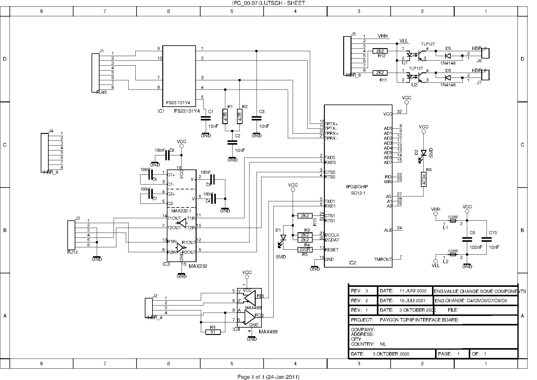
Pinout / Board desc
Top view
- (J5) +5v
- (J5) GND
- (J5) NC (not connected)
- (J5) NC
- (J5) NC
- (J5) NC
- (J5) Input optocoupler U1
- (J5) Input optocoupler U2
- (J4) NC
- (J4) NC
- (J4) NC
- (J4) NC
- (J4) NC
- (J4) NC
- (J4) NC
- (J4) NC
- (J7) Output optocoupler U2
- (J7) Output optocoupler U2
- (J2) rs422 -> max488 pin 5 (Y) --> Wire colors removed! They differ at boards. pin/wire layout won't (as far I can tell).
- (J2) rs422 -> max488 pin 6 (Z)
- (J2) rs422 -> max488 pin 7 (B)
- (J2) rs422 -> max488 pin 8 (A)
- (J6) Output optocoupler U1
- (J6) Output optocoupler U1
Top view CUSTOM HACKS
- (J5) +5v
- (J5) GND
- (J5) NC (not connected) <---- use for POE PLUS, connect to RJ45 at board? schematic/idea for 802.2af OR 7805 switch later. ask KingOfDos
- (J5) NC <-------------------- use for POE GND, connect to RJ45 at board.
- (J5) NC <-------------------- Solder this to the SC12 pin 31, I2CCLK?
- (J5) NC <-------------------- Solder this to the SC12 pin 30, I2CDAT?
- (J5) Input optocoupler U1
- (J5) Input optocoupler U2
- (J4) NC
- (J4) NC
- (J4) NC
- (J4) NC
- (J4) NC
- (J4) NC
- (J4) NC
- (J4) NC
- (J7) Output optocoupler U2
- (J7) Output optocoupler U2
- (J2) rs422 -> max488 pin 5 (Y)
- (J2) rs422 -> max488 pin 6 (Z)
- (J2) rs422 -> max488 pin 7 (B)
- (J2) rs422 -> max488 pin 8 (A)
- (J6) Output optocoupler U1
- (J6) Output optocoupler U1
Bottom view
Note:
- Pin17 @ SC12 = Link Led (connected to red led)
How to avoid periodic resets
- Disable tcp2con.exe in autoexec.bat
It looks like tcp2con.exe performs a device reset after 120 sec.
CGI HTTP
Default tools available:
- http://1.2.3.4/ChipCfg
- http://1.2.3.4/TCP2COM (reverse engineer, or write our own software)
Debugging
Hardware
"If it fails, the @CHIP prints the error message "RAM ERROR" on the COM port (using 19200 Baud and 8N1, regardless the entry in the CHIP.INI)."
Source: http://isa.umh.es/temas/micros/doc/sc12/doc/bootfc.htm
Software
Use TRACE.EXE (seen in manual, link page here!) or maybe use the remote SYSLOG daemon ( http://www.lourensrozema.nl/ax/download/syslog_src.zip is ASM! untested..)
Links
- http://isa.umh.es/temas/micros/doc/sc12/SC12V110_ReleaseNotes.pdf
- http://www.beck-ipc.com/files/api/scxxx/program.htm
- http://www.beck-ipc.com/en/download/index.asp <- choose SC12 in <select>box (at the 2nd block, @ bottom).
- http://wunderkis.de/scbrd/index.html
- http://isa.umh.es/temas/micros/soft/sc12/
- http://isa.umh.es/temas/micros/doc/sc12/
- http://xforce.iss.net/xforce/xfdb/8922 <- IPC@CHIP Web server root directory is set to the system root, aka, access all the files!
- http://www.openwatcom.org/index.php/Main_Page <- compiler for 16bit dos apps, that runs on linux
- http://www.weerschip.nl/download_beck.html <- weather station, with software examples (1 zip checked with 'grep -i beck *')
- http://www.lourensrozema.nl/ax/index.php?page=home.inc <- mp3 player + ide disk, incl some .zip files (schematics, sources incl remote syslog)
- http://www.psh-mikro.sk/beck/Beck_mod_de.htm <- CompactFlash something (schematic + demo program)
- ftp://212.71.131.133/pub/beck/software/
- http://www.zengers.net/index.php?option=content&task=view&id=12&Itemid=2 <- 3 pages uit Elektuur, Nederlandse manual (misschien uploaden op eth0 wiki?)
- https://wiki.bitlair.nl/Pages/Bestand:010036-11.zip de files van elektuur
Hackerspace working on/with them
- http://www.tkkrlab.nl/wiki/Beck_board_ipc_2001
- http://nurdspace.nl/IPC@Chip_boards
- https://wiki.bitlair.nl/Pages/Projects/SA12_IPC@CHIP
IRC
- network: oftc (irc.oftc.net)
- chan: #SC12


